
Electronic Attendance the Hard Way
This post hasn't been updated in over a year
In 2022, Keele University saw some huge organisation wide projects go live including an app based electronic attendance system. While this is a fantastic step forward and massive improvement of the student experience, it marked the end of an era for the electronic attendance solution I launched in 2015 as part of a previous role at Keele. In April 2023, after almost 8 years of use and a staggering 1,210,000 attendances captured, the final in-house attendance readers I built have been decommissioned.
It should go without saying; All information I've shared is for educational purposes only and provided as-is without warranty or liability. Using any information here to inform your own work is done so at your own risk.
During my time at Keele, I've worn many hats. Back in 2013 I joined the university as an IT Technician within the Faculty of Medicine and Health Sciences. About a year into my time at Keele, we started to look at how we could introduce electronic attendance to the Faculty. The Faculty of Medicine and Health Sciences run a number of courses that require students to receive a minimum number of hours of teaching in order to qualify with their governing body, so attendance is extremely important! Until this point, attendance across the entire university had been taken using paper registers. This caused no end of headaches due to the amount of time it could take for registers to make their way back to offices. Once the registers had been received, staff would then manually record attendance on various systems.
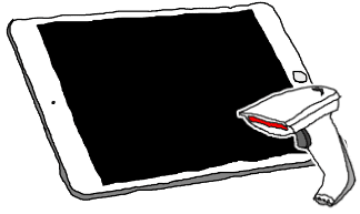
We started by trialing a number of inventive solutions such as iPads in kiosk mode mounted inside rooms, as well as battery powered barcode scanners. The barcode scanners at first worked but didn't scale very well as they required a lot of manual intervention to map attendances to students and sessions.
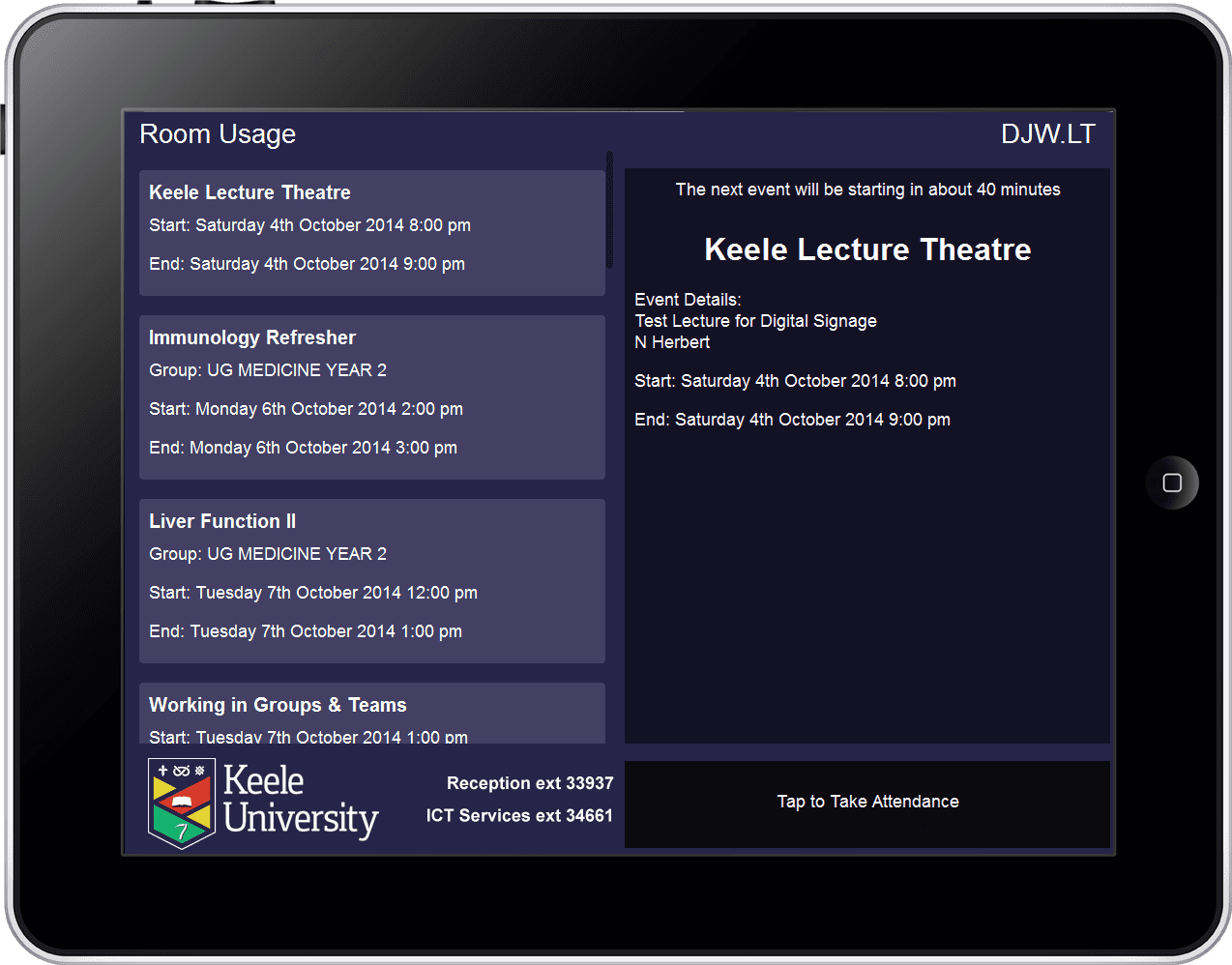
For the iPads, I wrote an app which integrated with our timetabling software Celcat. The app showed room availability and allowed lecturers to take a register using Celcat.
Though the iPad and Portable Barcode scanners worked, neither solution were ideal. While paper registers were mostly left to the students to do, both of our solutions put the emphasis on the lecturer to take attendance, which didn't go down very well! We also investigated a number of attendance readers from external companies. Based on feedback from the first trials, we knew that we needed dedicated, self-service devices that required no input from staff to process. Unfortunately, the eye watering price tags for these types of devices resulted in us being laughed out of budget meetings!
In January 2015, being frustrated by the cost of devices, I stupidly said:
"It can't be that hard, why don't we make our own [attendance readers]?"
So, I set out to make a proof of concept electronic attendance reader. The goals were to create something that would be fast, could read data from our ID cards and be cheaper than any external solution. After some quick prototyping with an Arduino it looked like it would actually be a feasible project.
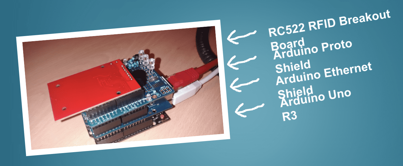
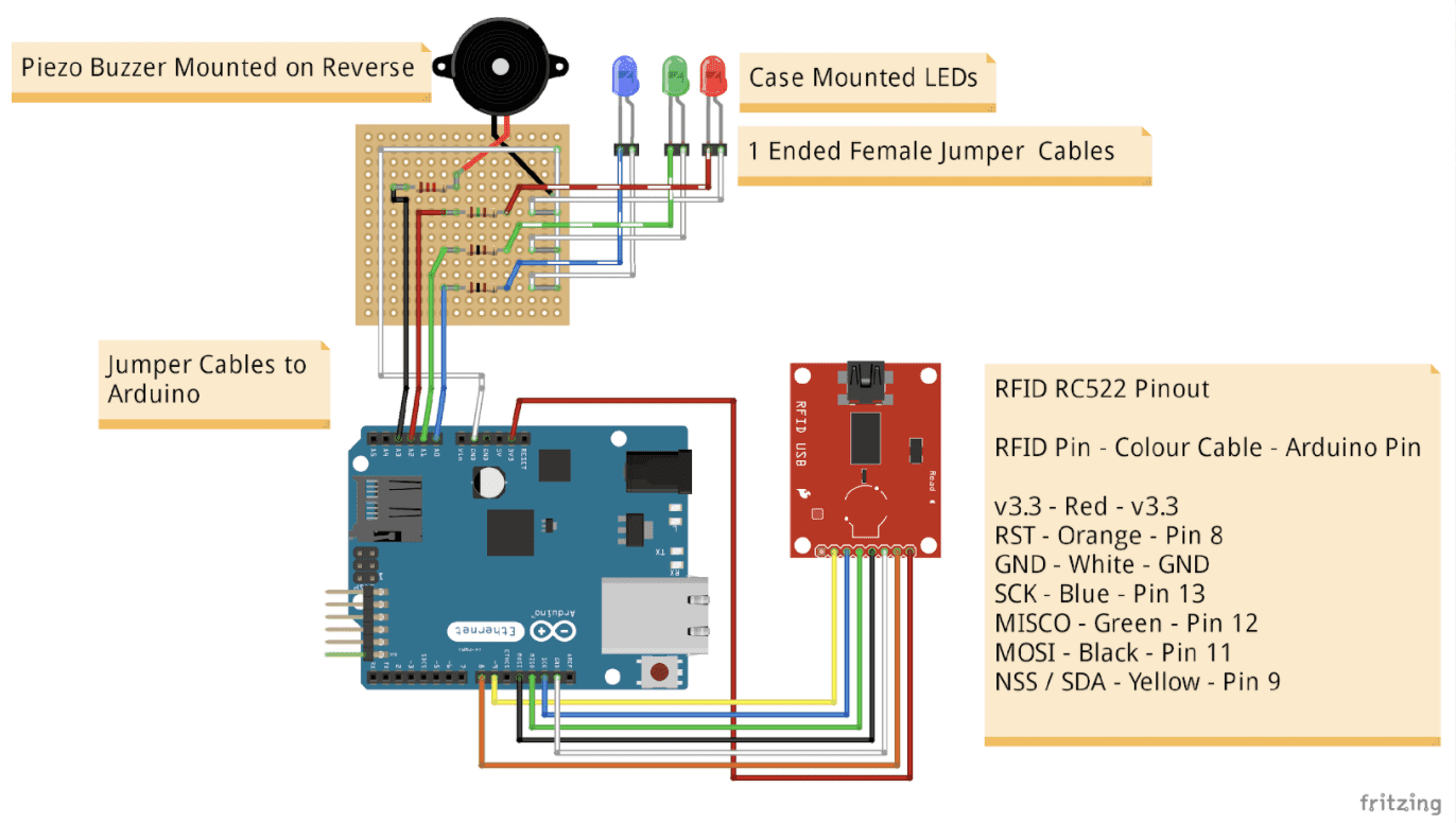
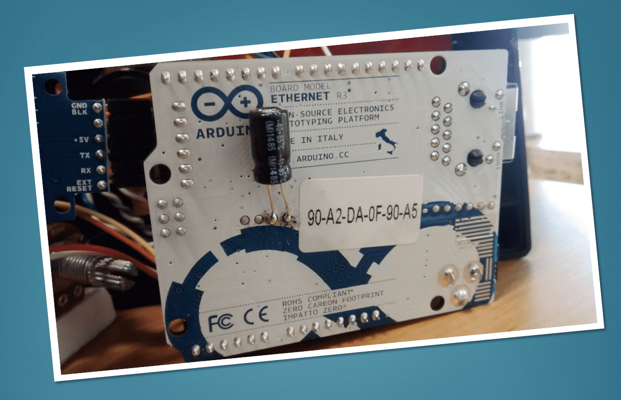
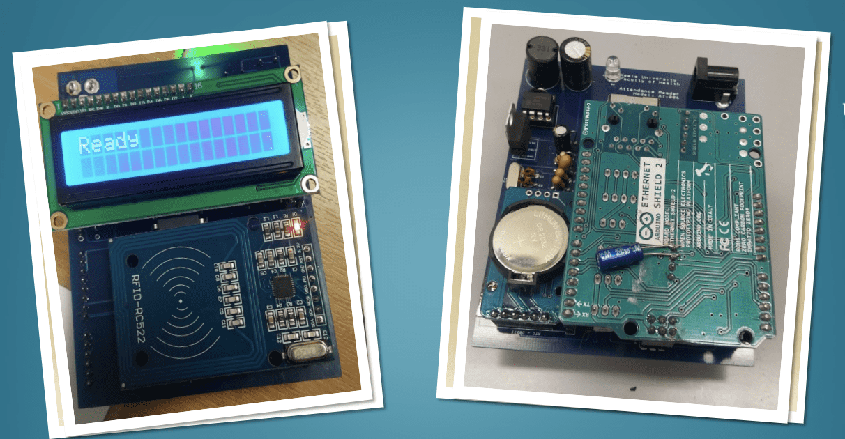
The prototype consisted of an Arduino Uno R3, an Arduino Ethernet Shield based on the wiznet w5100 chipset, an Arduino Proto Shield, an RC522 RFID Breakout Board, some LEDs and a piezo buzzer. All of these parts came to a grand total of just under £15, a fraction of the cost of an off the shelf device! At the time, our ID cards were Mifare Classic which could easily be read. The prototype had Red, Blue and Green LEDs as well as a peizo buzzer to provide accessible feedback to the user. The Arduino Uno R3 made use of an Atmel ATMega328, an 8-bit microcontroller with a rather sparse 32 kb of code space and just 2 kb of ram, not giving us room for much more than that needed for an MVP.
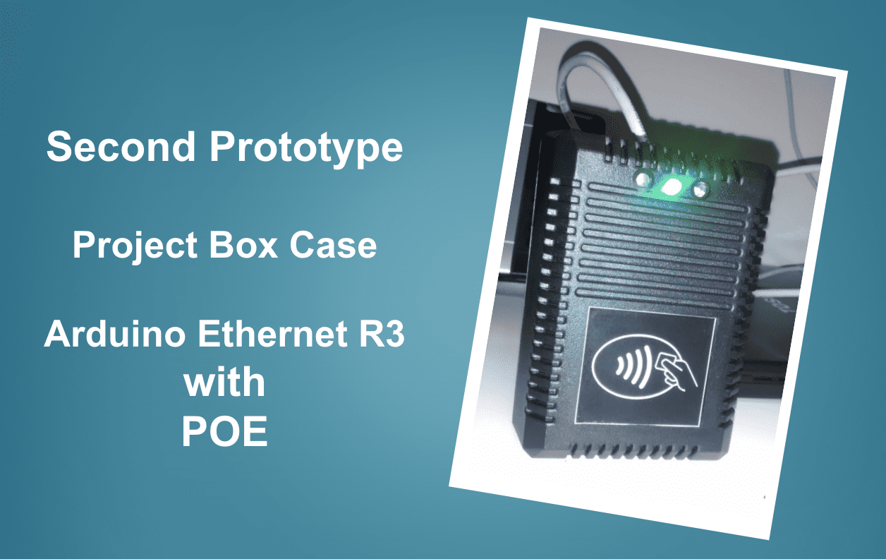
A second prototype was put together, this time with a case and an Arduino Ethernet R3, which combined an Uno R3 and a network shield into a single board. It also had a power-over-ethernet (POE) module to receive power directly from the network cable. At this point a colleague had knocked together a basic web application in ASP.net to capture card data being sent from the prototype.
This device sat in our office for a number of weeks with anyone coming and going being asked to scan their cards so we could test it.
The main issue with this version of the prototype was with feedback. The feedback was so quick and would rely on users needing to know what certain flashing or buzzer patterns meant, it wasn't as intuitive as it could be. We also couldn't give people other useful information such as a headcount of how many people had scanned in or even the time.
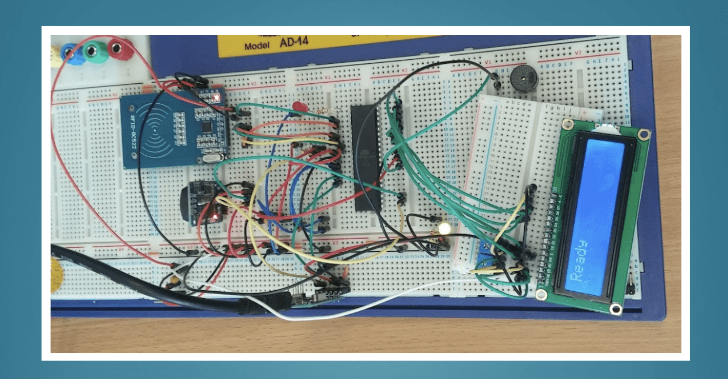
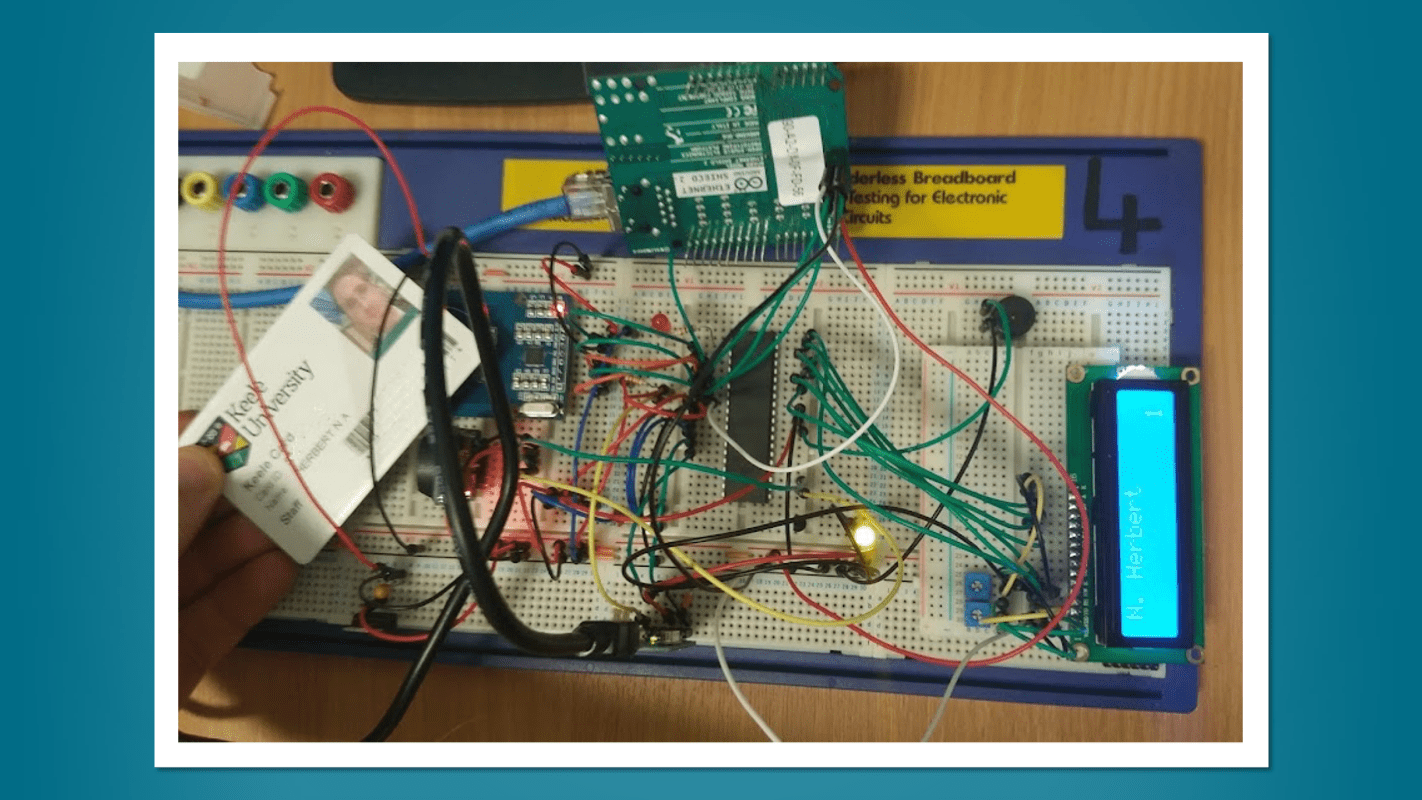
Not happy with the feedback side of things, I added a screen and attempted to make something a little more solid with perfboard. The board used header pins to allow us to easily replace components such as the 16x2 screen.
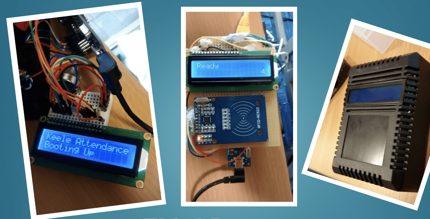
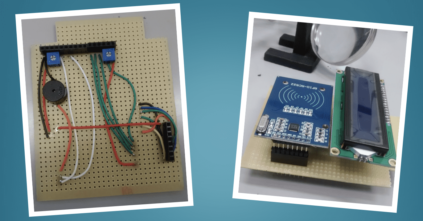
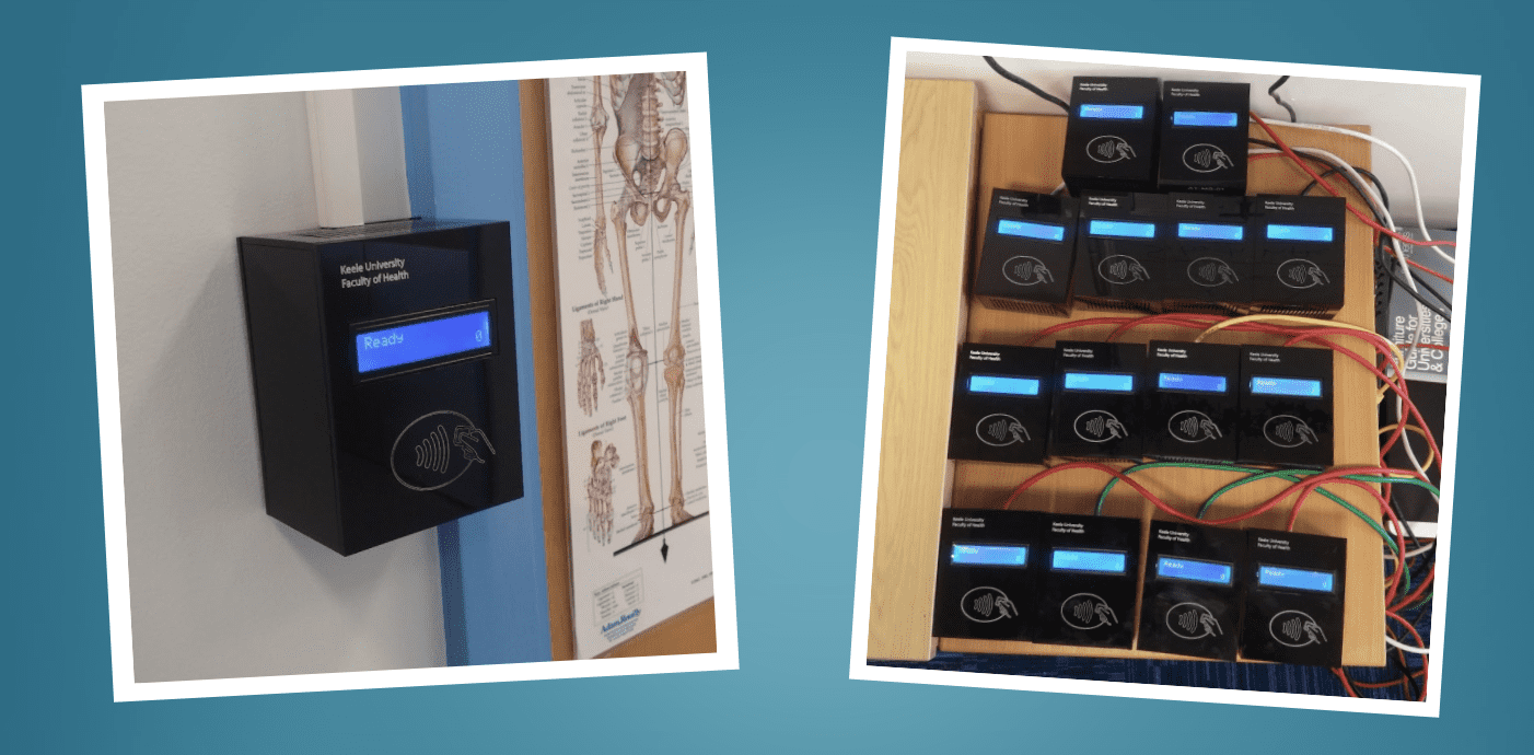
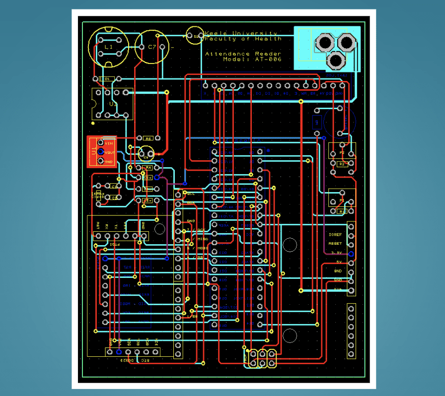
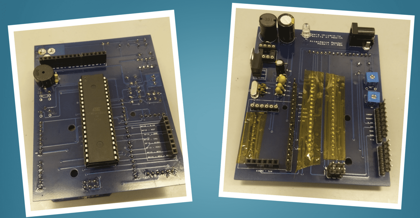
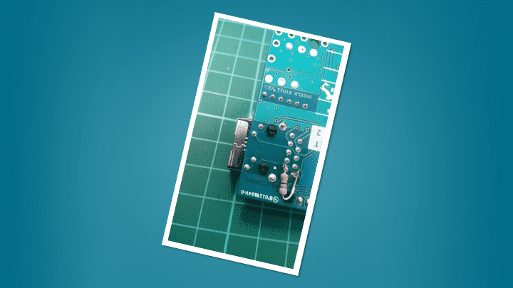
In March 2015, I had the go ahead to create a small number of devices to pilot in real rooms. This led to a colleague designing a laser cut case to give them a more polished look to the project box we had used for the prototype. The perfboard design was translated into a PCB to make it even more resilient. The key with our design at the time was to use readily available, low cost, off the shelf parts. If something broke, it could easily be replaced without having much knowledge of the inner workings of the device. The PCB was purely there as a way to reliably connect the components together.
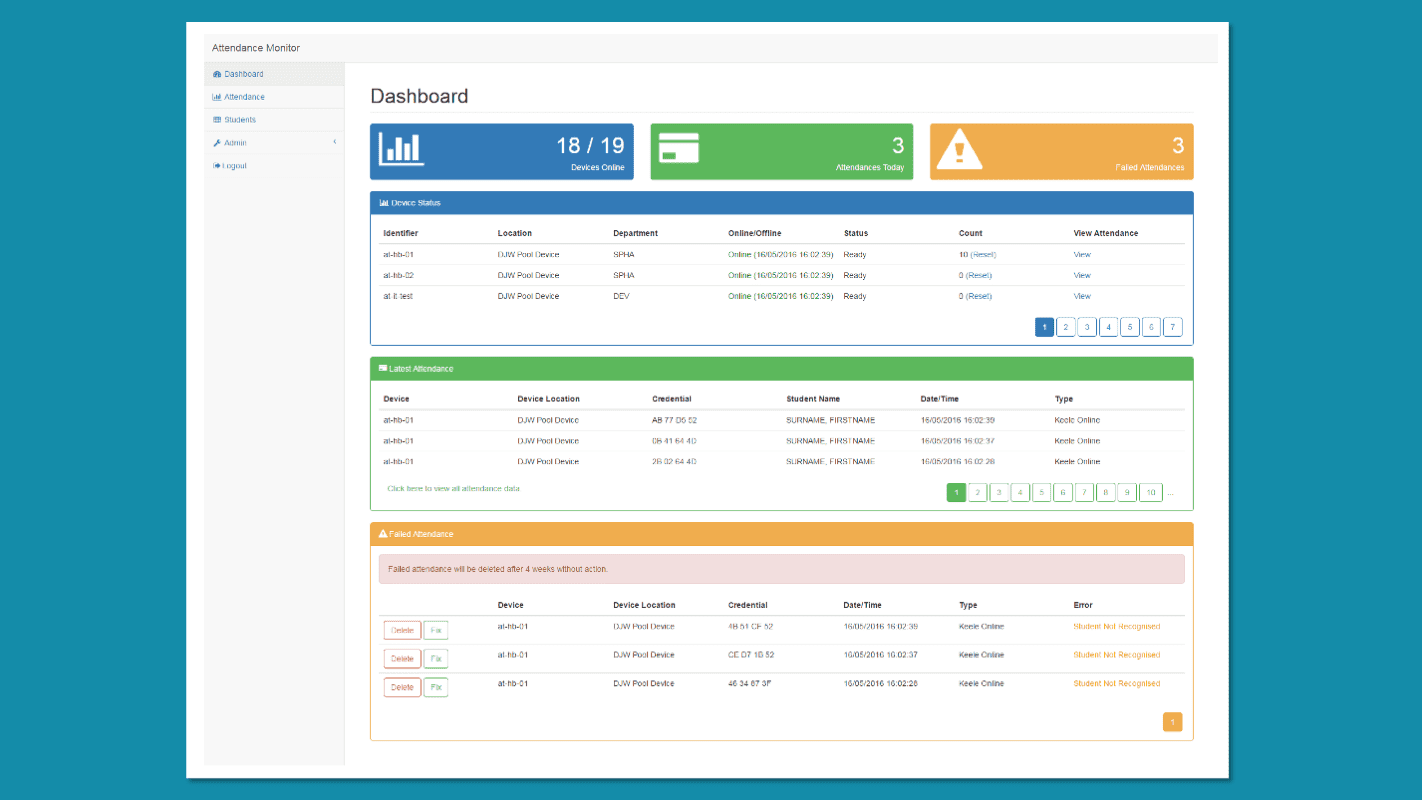
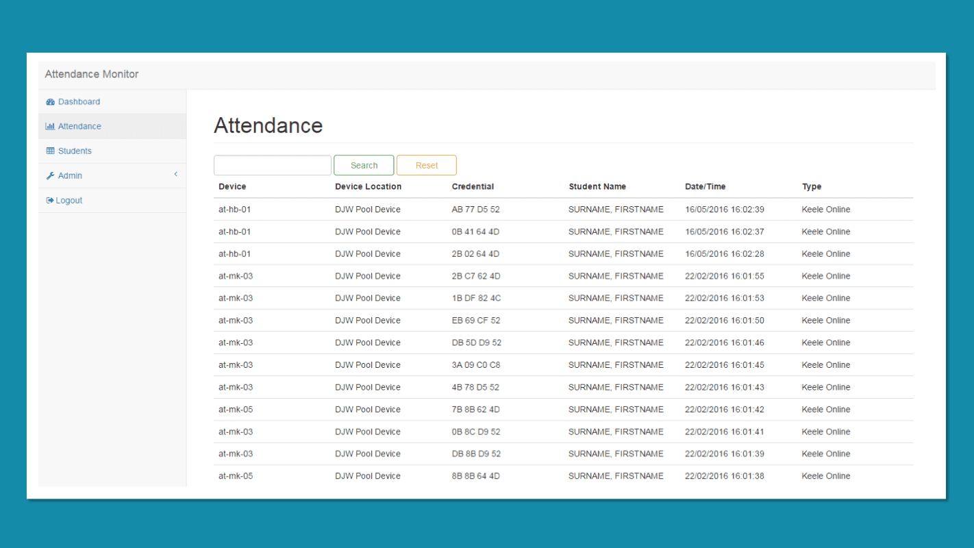
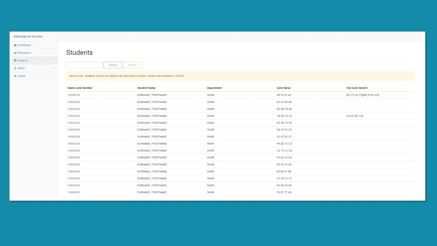
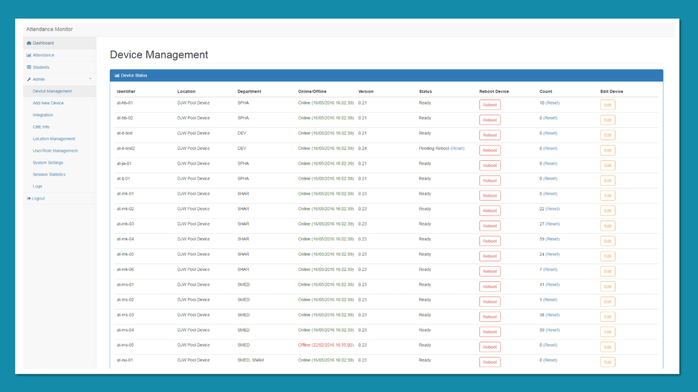
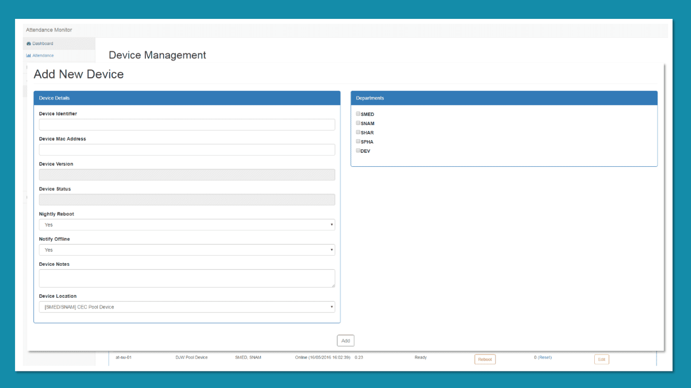
Though we had the hardware solution to capture attendance, the server side had been extremely basic until this point. A colleague set about writing a web application which included a number of features such as an API for the devices to talk to, integrations with our timetabling and attendance system, a dashboard and a section to manage the devices. The device management included the ability to reboot the device, test the LCD screen and test the buzzer.
Initially 14 devices went live for the start of the 2015 academic year. We fitted all rooms in one of our smaller teaching buildings and the rest were placed in busy rooms such as labs and lecture theatres. The sessions in those rooms would run back to back and couldn't cope with delays. The paper attendance registers for labs would be done as students entered the room causing delays in the session starting. Sessions that didn't start on time would overrun and cause the next session to start late which in turn would start even later due to the attendance process. Taking an attendance register in a lab with one of our devices was a game changer. One of the quickest registers we have on record took 1 minutes 18 seconds for 42 students, a drastic improvement on what could take anywhere upward of 5 minutes with paper.
After a few weeks we started to receive complaints of a high pitch squeal coming from most of the devices. I hadn't noticed this during development or install. After some investigating, it looked like the issue related to the device being powered by POE over long cable runs. During testing, the devices had mostly been powered by USB, or a POE injector on my desk, in either case the network cable being used was relatively short. Our first port of call was to check-in with the company who made the POE modules, Silvertel. They spent some time trying to replicate our problem and came back with an answer and an explanation. It turned out that Arduino had swapped to a cheaper POE module and not updated their board spec to accommodate it. The docs for the new module required a different capacitor to the old module, which Arduino hadn't changed. The older POE module had included a cap which wasn't present on the cheaper version, hence having a different requirement. The answer was to add a capacitor across certain pins on the Arduino board.
Not long after we fixed this issue, we started to receive requests to extend the pilot. We agreed and another 10 devices were built and installed.
Unfortunately, while we were working on the new devices, a number of events unfurled that drastically changed the direction of the project. It had been announced that the technology being used for our ID cards would be changed. After getting our hands on one of the new cards we found that the RC522 RFID boards we had chosen could not read them. The bigger blow was that Arduino had discontinued the Arduino Ethernet R3. Both show stoppers for the pilot devices. Looking back, we should have just called it a day! However, at the time, this allowed us to explore further options as I already had concerns with how we would actually implement some of our requirements. When we had originally started the project, we had a huge list of requirements and features, but we just couldn't fit many of them into an MVP. A major request had been to provide offline and mobile attendance, portable devices that could be taken to any location. The issue we had with implementing this came down to the available code space on the ATMega328. I'd almost filled the thing with the life support and api calls.
The ID card issue wasn't a big problem to solve. We could switch to a more expensive RFID board that used a PN532, a chip that could read the new cards. However, this would increase the device costs by almost £20 each! A slight pain with the new RFID board was that it had a different pinout, this meant that we had to create adaptors for the existing devices. On future PCB designs we included a way to remap the pins using through-holes and solder jumps.
The more pressing issue would be what to do about the Arduino Ethernet board. It was a nice board as it combined 3 things we needed into a single, smaller footprint. The next board Arduino offered at the time with more code space was the Arduino Mega, but the footprint was huge so not an option! No matter what, it looked like we would need to have a separate microcontroller and network boards going forward.
After a lot of search-engine-fu, I came up with an answer. We would have to move away from the off-the-shelf components. If we switched to another pre-made product such as a Teensy, what would we do when that would inevitably be discontinued? One of the alternatives were to switch to a raspberry pi, but I felt a full-blown mini-computer, with a full OS was overkill and would be too slow to boot. In my search, I came across the DIP version of the ATMega 1284 which gave us 128 kb of code space and 16 kb of ram, something we could definitely work with! The only issue with the 1284 was that it wasn't officially supported by Arduino, luckily there had been some work on this already within the community, and it was possible to get the Arduino bootloader onto the 1284. You are probably wondering why we didn't just switch to something like Atmel Studio? The Arduino platform made it extremely easy, a lot of boilerplate code was already there, especially for networking. Moving to a different platform would be a bit of a steep learning curve and would take some time to figure out how to do things like networking.
After some trial and error I had the 1284 working and started to work on designing the PCB. Starting from scratch and having more code space, I added over-the-air updates to help us manage large numbers of firmware updates. I also added a real-time-clock (RTC) to allow us to keep the time when the device wasn't connected to the server, a massive tick towards offline and portable attendance. While designing the new 1284 based device, Arduino had replaced the ethernet shield with a v2 that used a different chip the wiznet w5500. As far as we could tell, this just required us to update the library we were already using, along with the additional capacitor.
In January 2016 we held a review meeting to decide the fate of the project. Everyone involved from across the Faculty seemed really happy with the results and wanted the devices everywhere! Despite the set backs the group decided to try the 1284 based custom device.
By May 2016, I had tested the 1284 and was confident enough in it to be given the green light to roll it out to the entirety of our hospital campus. 54 new 1284 based devices would need to be made and installed before the start of the new academic year in September 2016.
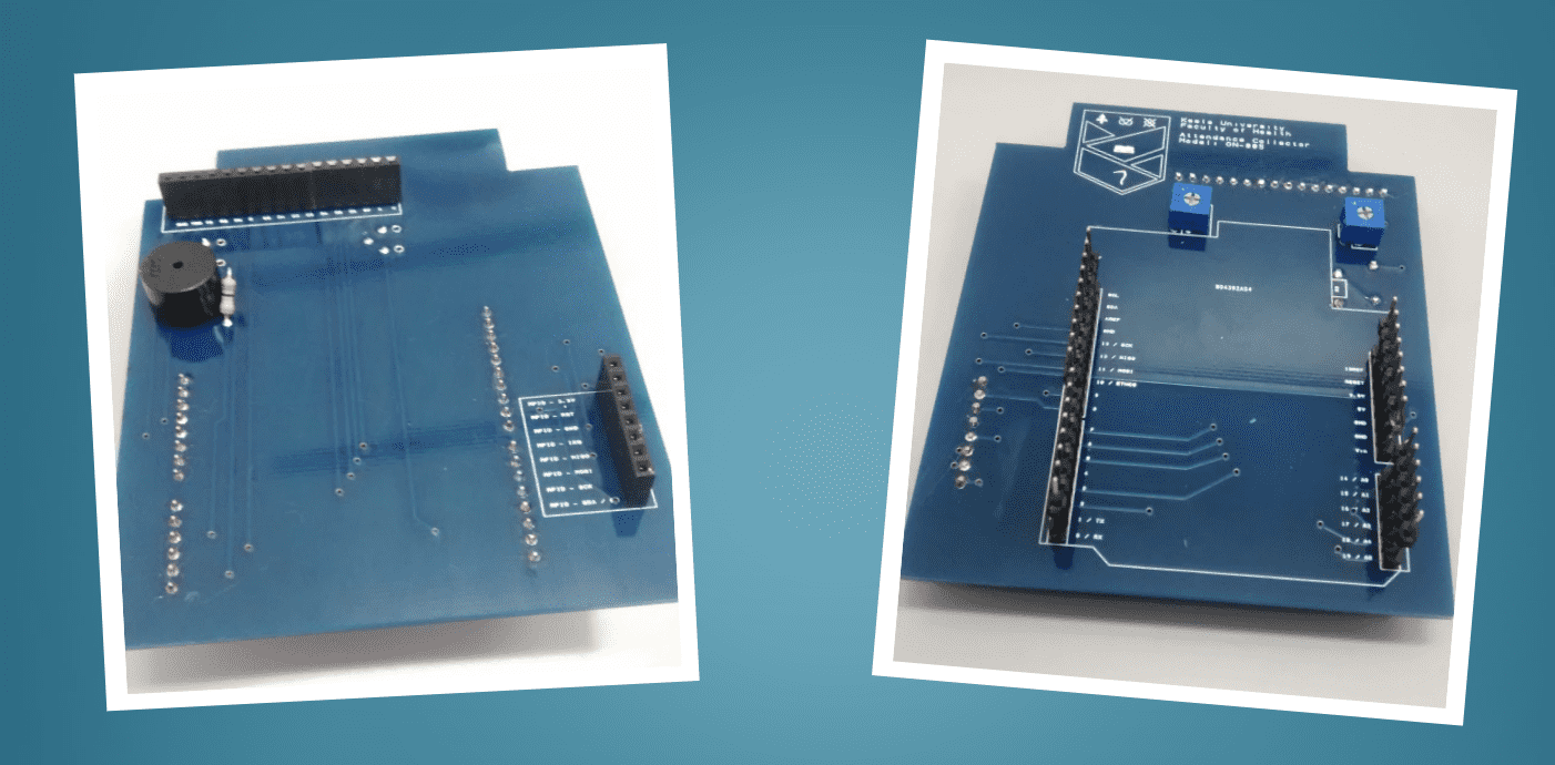
You might be looking at the breadboard and PCB above and be wondering about the design decisions. I'm no expert when it comes to electronics and a lot of what I put together was a result of trial and error. The crystal for example is usually put as close to the microcontroller as possible. I found it to be extremely unpredictable when it was too close. For the screen, it was hard to put a fixed resistor in for the brightness and contrast. We needed to be able to change it depending on how the device was being powered and how long the network cable was. Using micro potentiometers allowed us to tweak the resistance without much hassle.
By mid-September, it was all hands on deck. All 54 devices had been built and the rooms had been prepped for install. A team of colleagues were all ready to get the 1284s on the walls when disaster struck during the install of the first device… it wouldn't talk to the network… I had built and tested each device myself! Each one happily spoke to the server at my desk. Expecting it to be an isolated issue, we continued the installations… but then the second device wouldn't talk, then the third, then the fourth. Oh no, something was majorly wrong and the entire deployment ground to a halt, looking like it would be an epic failure. What on earth was causing the issue? Was it an environment issue such as a problem with the networking equipment in the building? Were the devices misconfigured for the vLan on those network ports? My worst fear was that there could be a fundamental issue with the device, despite testing?!
A few frustrating days later, I found the issue. The device worked when I used the v1 ethernet shield (w5100). Due to lack of availability of the original, we had intended to use the new v2 (w5500) ethernet shields. To get the installations back on track we used as many v1 boards as we had, while I troubleshooted the v2 ethernet shield. The issue turned out to be that the magjack on the v2 board didn't include the required resistors. Yet another change to make the board cheaper without updating the design! This led to a resistor being soldered over 2 of the pins on the magjack. In hindsight, I should have added another to the other set of data pins as well!
After this very simple addition, the project was back on track with all 54 devices being installed and ready for the start of the academic year. Despite having to replace a couple of the real-time-clocks and a number of screens over the next academic year, the new devices worked well. I had made a slight error in the firmware which caused the LCD screens to burn out pretty quickly due to the rate the screen was being written to. Once I'd lowered the number of writes to the screen, the burnout issue was drastically reduced.
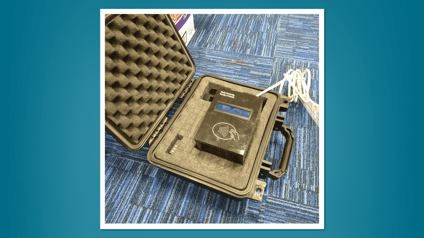
With the success of the new devices, we planned to roll out to the rest of the faculty for the start of the 2017 academic year. The original pilot devices would be replaced with the newer version, we would also include some additional portable readers. Each school would get at least one portable reader which could be used offline and as a working spare if needed. One of the schools heavily relied on poolrooms or shared rooms, which meant they had no guarantees of which rooms their sessions would be scheduled in. For this school, we created as pool of six portable attendance readers as it wasn't viable to fit nearly 300 additional teaching rooms on the off chance of it being used by our faculty. The functionality for offline attendance had already been written and rolled out as part of the wall mounted devices installed in the summer of 2016. As for the hardware, we just needed a way to safely transport and power the device. The final solution was to house each portable reader in a small, black plastic flight case, the inside of the case had a foam insert that would have a cutout for the reader to sit in. The reader had a network cable and a POE injector to power the device (I was reluctant to make them battery operated due to various concerns). The devices would live at the school's reception where a lecturer would visit to collect a reader for the day. Once returned the reception team would connect the network side of the POE injector to the network and the device would upload its card scans, report health metrics and ensure the real-time-clock was in sync.
On boot, the device would perform a number of self-checks to ensure that the device had a working real-time-clock, a working micro-sd card, a working RFID Card reader and finally network. If any issues were detected and as soon as the device was online, it would report them back to the server notifying us that a repair was required. The boot also determined how the device would operator. If network was available at boot, the device would act as a wall mounted device, attempting to check in with the server every 60 seconds. If the device lost network while in this mode it would go into an offline mode but would attempt to regain a connection until it could talk to the server. Before becoming ready for use it would check to see if it had any offline attendance to upload to the server. If network was not available at boot, the device would go into offline mode where it wouldn't attempt to check in with the server or gain a connection.
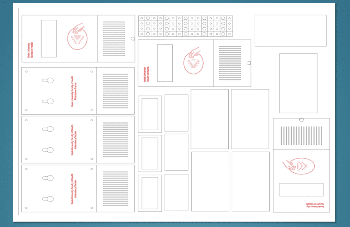
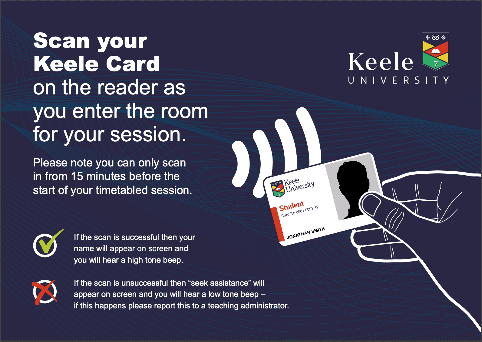
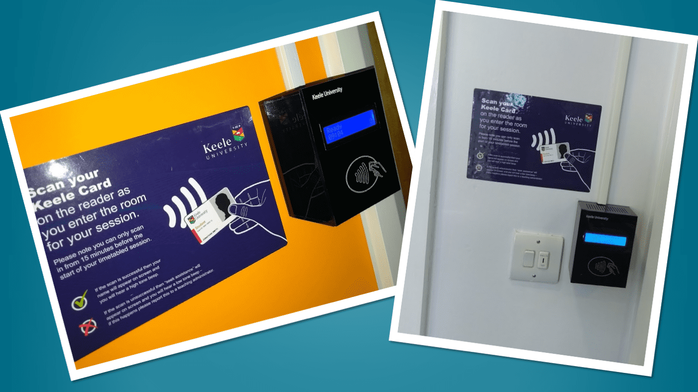
Something that had been playing on my mind as we approached the next rollout was a particular question we constantly received. "At what point can we tap in for our session?" We would see people tap in anywhere upto an hour before their session which wouldn't get registered! This lead us to asking marketing to create a poster that we could put next to each reader. We had the poster printed as a vinyl sticker, so it would last and would be easy to put up.
By September 2017, we had rolled out attendance readers to all the rooms within the faculty with almost no issues. We had deployed a total of 110 attendance readers since starting the project and now provided electronic attendance to a third of the university! Our devices were so successful we had visits from a number of other universities wanting to see what we had done. We were also invited to tender for the university wide electronic attendance project. We presented our solution, but the university chose to implement electronic attendance using the university's existing app which made use of bluetooth beacons in each room.
I really enjoyed working on this project and am super proud to finally be able to share some of the tech behind it. I am sad but also relieved to see it decommissioned. Relieved as attendance is a critical component within a University and a lot of pressure to get right and make sure it all remains working! It was an extremely steep learning curve having no background in embedded electronics! In hindsight, we really should have called it a day when Arduino discontinued the Ethernet R3. We had originally set out to make something that was extremely easy to run and maintain. Having to pivot to a completely custom solution had its benefits, but it was a real strain on a very small team to look after. The final design of our device cost us around £60 in parts and did exactly what we needed. All off the shelf readers we looked at didn't have core features we needed such as headcounts, clocks or offline attendance, they also couldn't compete with the price point we were able to develop something at.